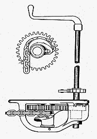
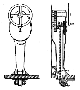
 The standard handbrake on most trams. This is a drawing of the Peacock brake, where a chain connected to the brake rig is wound round an eccentric drum, so that the first movement of the handle quickly took up the slack in the chain.
|
Starting & Stopping
Tramcar Controllers and Brakes By John Prentice |
Having got our tramcar moving, we have to stop it again and if necessary to park it. If placed in the "off" position, the controller will allow the tram to coast. To stop it you have to apply brakes fitted to the Tramcar Trucks.
The type of brake used for normal stops on British trams up to around 1906 is the hand-applied wheel-brake, inherited directly from the type used on Horse trams. At the top of a vertical shaft, known as the brake staff, at the Motorman's position (right hand) either on the platform or fitted to the outside of the dash plate, is a cranked handle, usually fitted with a ratchet so that the most comfortable position can be chosen. At floor level was a foot operated pawl to hold the brake on for parking.
The standard handbrake on most trams. This is a drawing of the Peacock brake, where a chain connected to the brake rig is wound round an eccentric drum, so that the first movement of the handle quickly took up the slack in the chain.
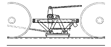
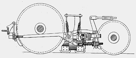
On turning the handle clockwise a chain below the floor is wound around the shaft (later geared drums) and pulls on a sway-bar in the centre of the tram (can be done from either end of the car), which in turn by rods pulls on the brake beams which cause cast or soft iron brake shoes to be pressed equally onto the treads of the wheels. For bogie cars the brake rigging includes a radial beam or archbar on which a pulley runs on the inner face, so that the brake action is the same regardless which way the bogie is turned. Most British trams retained a conventional hand brake for parking, despite future brake developments for the service stops.
For emergency stops electrical braking was used, being applied by brake notches on the controller. In its simplest form the motors are simply shorted out or even put into reverse. A more sophisticated method allows the current generated by the turning motors to be used up by the resistances (turned into heat) which are put in parallel with the motor and then progressively cut out until the motors are fully shorted out. While quite effective this form of braking can overheat the resistances, so is not suitable for the normal service stops. Instead of just wasting the electricity, regenerative braking systems can feed it back into the current supply, such a design being used by John Smith Raworth on his demi-cars and covered by British patent 3658 of 1903. Regenerative braking was not widely used by trams in the UK, although after experiments on a number of tramways in the 1930s, Glasgow operated 40 such cars. However, it was frequently employed by trolleybuses, particularly on the extensive London network.
In the UK the Board of Trade (later Ministry of Transport) determined the regulations and decided that hand operated wheel braking could only be used up to 16 miles per hour (less in some specific cases). Track brakes are a possibility, but care has to be taken as pressing a shoe against the rails by mechanical means has the effect of decreasing the weight and adhesion of the wheels which will then slip or even derail. In 1906 the London County Council devised a magnetic track brake based on the earlier Westinghouse magnetic track brake. It became standard on all their cars, and other tramways and manufacturers used similar products.
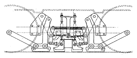
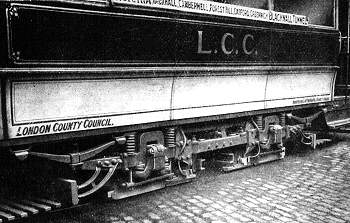 The magnetic track brake. This view shows magnetic track brakes fitted experimentally to a London County Council class C car in 1906, one each side of the central plough carrier. This type of brake became the L.C.C. standard but the experiment wheel guards that can also be seen were not continued with.
With the magnet track brake, the current generated by the motors is fed via the resistances into electromagnets on track brake shoes. These are then attracted to the rails and the friction there, plus the electrical braking effect of the generating in the motors, slows the car. In the case of the L.C.C. brake, the backward drag on the brake shoes was linked by levers to apply the wheel brakes as well. All the Motorman then had to do was apply the hand brake for the final stop (all such electrical brakes decrease in effect as the car slows).
Air brakes had been common on American trams in the 19th Century but although early designs exist, such as on the Brill cars in Liverpool in 1898, they did not find great favour in the UK until further speed increases were required in the 1920s. Such brakes on trams use a compressor pump, either with its own electric motor or occasionally axle driven, to fill a reservoir with compressed air. Via suitable valves and brake cylinders, the air can be used to apply wheel and/or track brakes powerfully. To ensure that the car's air brake was applied before its electrical braking, there was often an interlock, such as that designed by Alfred Maley in 1914 and sold by EMB and later Maley & Taunton.
 The Snaefell mountain line on the Isle of Man uses the Fell system, designed by John Barraclough Fell but installed by his son George Noble Fell, where horizontal flanged wheels engage on a third rail to prevent derailments. This calliper slipper brake operated on the sides of that rail and was employed throughout the decent, although since 1982 modern rheostatic braking has been used instead and the Fell brake is now reserved for emergencies only. (Photo by J.Prentice ©)
For steep hills the Board of Trade imposed special conditions, the usual one being that some form of slipper brake be used. This was a track brake that could be wound on at the top of the hill and then kept on throughout the descent. It had to be separate from the usual braking system. It was usually applied by a hand wheel mounted on the brake shaft just below the usual cranked brake handle. There were some special versions of this for certain tramways. For instance the Snaefell line on the Isle of Man had a brake operating on the Fell rail. The L.C.C. conduit electric tramway on Highgate Hill and the Swansea Constitution Hill cable tramway both had brakes that gripped their centre slot rails.
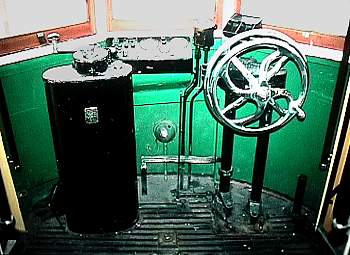 The control position on a Lisbon car in 1993 shows the Dick Kerr controller on the left and the double vertical brake hand-wheel on the right, the two wheels activating the normal wheel parking brake and the track slipper brake. In fact these "hilly route" cars had six separate brake systems; air-wheel, hand-wheel, air-track, magnetic-track, hand-track and runback. (Photo by J.Prentice ©)
Clearly the tramcar brake was a rich field for the inventors of the day, with far too many to mention here, but the following are some of the common names and patent devices that the tramway student will come across.
In the UK the most common type of hand brake system was the Peacock (drawing at Top of Page), which was widely advertised at the time in the tramway press. It originated in the US being designed by John Langford Peacock of Buffalo, N.Y. and in Britain was covered by patent number 19,770 of 1903. Its unique feature was that a geared winding drum was eccentric so that the first movement of the handle quickly took up the slack in the brake chain, but subsequent movement exerted greater pressure. A modified version of this brake staff had a hand wheel to apply slipper brakes, mounted just below the cranked handle.
 The Ackley Vertical Wheel Brake Handle.
The original Ackley system was a similar geared drum brake to the Peacock and was also used in the UK. It too originated in the US with a design by Charles Sexton Ackley of New York covered by British patent number 8690 of 1901, with subsequent patent improvements by Griffin S. Ackley of Buffalo, N.Y., where they were made by the National Brake Company. The unique feature of the Ackley was that is was made with a set of standard parts which could be used on any tram irrespective of the brake position or the bumper or platform thickness, cutting down manufacturing costs and spare part stocking. British patent number 2813 of 1911 by Charles Sexton Ackley was for a winding mechanism with vertical wheel, which took up little space on the platform and had the gear mechanism above the floor and enclosed to keep out dirt. Handles of this general type were often used on later trams where the handbrake was only used for parking.
Elmer Elsworth Cook had worked for the McGuire company of Chicago in the US and in 1900 came to Britain to set up and take charge of the truck workshops at the Falcon Works of the Brush Electrical Engineering Co. of Loughborough. His initial truck designs certainly had a similarity to those of McGuire, but in addition he took out British patent 21,797 of 1902 for a pneumatic tramcar brake. This used an axle driven pump to supply air directly to brake cylinders operating on wheel and/or track brakes. The use of this brake never caught on and it was some 20 years before air brakes became popular in the UK, but this is certainly an example of a very early UK design.
Christopher John Spencer of Halifax, Yorkshire, started his tramway career in 1889 with Michael Holroyd Smith, a fellow Halifax man, in Blackpool. After working as an electrician from 1892 with South Staffordshire tramways where his father, Frederick Spencer, was Resident Engineer he became General Manager in Bradford in 1898 and ultimately managed the "Underground" group companies Metropolitan Electric Tramways, London United Tramways and SouthMet from 1918, becoming General Manager, Tramways (North and West) with London Transport in 1933. To cope with the hilly routes in Bradford, he designed a slipper brake, covered by British patent number 17,986 of 1899. Using a simple system of levers controlled by a hand wheel, a wood faced track brake shoe was pressed onto the track for continuous use on the descent of hills. The Spencer slipper brake was used on many tramway systems thoughout Britain.
In 1898 Frederick Spencer mentioned above became manager of the new tramways in his home town of Halifax. Due to the hilly nature of the routes, cars were fitted with the slipper brakes designed by his elder son, C.J.Spencer. However the degree of wear on the brake shoe was excessive, so Frederick Spencer's younger son, Charles Henry Spencer, who was then the Rolling Stock Engineer at Halifax, designed an improved version covered by British patent number 6262 of 1907. This used a metal brake shoe, some 39" long to cut down the wear and improve braking effect. This was then used on all Halifax cars and was also employed in Huddersfield, Oldham, Ashton and the S.H.M.D. tramways.
The Spencer-Dawson oil operated brake system was designed by Christopher John Spencer and John William Dawson and covered by British patent number 8740 of 1911. This was a fail safe system where a track brake was held in the "on" position by powerful springs and was released by hydraulics (it could be manually wound off if no oil pressure was available). The oil used for the operation was kept in a reservoir, together with air under pressure. The necessary pressure was obtained from an axle driven pump. The brakes were controlled from a single lever at the driver's position, it having the following selections:- "Off" caused the oil pressure acting on the brake cylinder to oppose the springs and release the brakes; "Coasting" allowed the springs to apply the track brake and was used for descending hills; "Full-On" used the oil pressure to add to the spring pressure on the track brakes; "Wheel Brakes On" used a separate cylinder to apply the wheel brakes. This brake's use included some routes in Birmingham, Bradford and the Metropolitan Electric Tramways in London.
Alfred Walter Maley of Leeds took out his British patent number 28,306 in 1906. This covered a form of electro-magnetic track brake where when the magnetic brake shoes contacted the rails, the action of pushing them backwards employed levers that would apply additional brake shoes mounted to either side of the main shoes, distributing the friction over a much larger area. If necessary the brake could be operated by methods other than just the electro-magnets to provide say a slipper brake. The Electro-Mechanical Brake Co. (EMB) was originally set up in West Bromwich by Maley and others in 1908 specifically to sell this device.
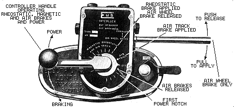
By 1913 EMB was owned jointly by Maley and the Cadbury Family (of chocolate fame) with George Norman Cadbury as Managing Director. In 1914 Maley took out British patent number 6443 of 1914 jointly with G.N.Cadbury. This covered the Air Brake interlock which was used on British and overseas tramways for many years. It combined the use of electric braking with air (wheel or track) brakes. It was fitted to the top of the controller and usually incorporated an air brake handle, although sometimes this was separate.
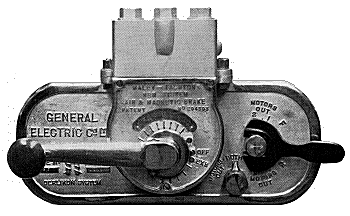 A Maley and Taunton built version of the interlock fitted to a General Electric Co. Ltd (the British company) controller.
The device ensured that the electric brake could not be applied before the air track brake, and to avoid wheel slip the the air wheel brake was released before the rheostatic brake was deployed. In general terms the first brake notch or the brake handle applied the air brake to wheels or track. Subsequent brake notches added rheostatic or magnet track braking. Setting the controller back to "off" left the car held on the air brake. Moving to the first power notch released the air brake. In 1926 Maley left EMB taking with him Edmund Taunton, their Chief Designer, and together they set up Maley & Taunton Ltd. in Wednesbury. Both EMB and M&T continued to sell versions of the Maley Interlock.
In 1898 Frank Clarence Newell of Chicago (later of Wilkinsburg, Pennsylvania) designed a form of magnetic track brake basically defined in US patent number 616,956 of 1899 with details in US patents 667,246; 667,729 and 667,730 of 1901 and also covered by British patents 9059 and 9060 of 1900 and 998 of 1901. The patent rights were assigned to the Westinghouse Air Brake Company of Pittsburg, Pennsylvania. In this device a magnetic track brake was applied by the usual method of using current generated by the motors (via the cars resistances and a specially designed Westinghouse controller). The friction with the track caused the brake shoe to be pushed backwards, which by a system of levers applied the car's wheel brakes. An improved version of this brake was used by the L.C.C. tramways after 1906.