
By David Voice (with additions by John Prentice)
|
|
TRAMCAR TRUCKS
By David Voice (with additions by John Prentice) |
 WHAT IS A TRUCK?
Firstly what do we mean by trucks in a tramway context. Well unlike railways, where Thomas the tank engine's troublesome trucks spring to mind, tramway trucks are actually an integral part of the tramcar. They are the device that holds the motors and wheels in place, and attaches them to the body. In a sense the truck is the chassis of the tramcar. There are two distinct types of truck. There are four wheel tramcars, where the truck is held in line with the body, and there are bogie tramcars, where there are two or more small trucks, which can swivel in relation to the body. This is our first complexity. In Britain we call the first trucks and the second bogies (though in an early photograph of a four wheel tramcar the caption reads "A single bogie tramcar" indicating that in early times the word truck was not used). In America they are much more consistent and the four wheel tramcars have a truck and the others have double trucks. They do not use the term bogie. Having confused you already I will look at each type in turn in the hope of bringing some clarity.
FOUR WHEEL TRAMCARS
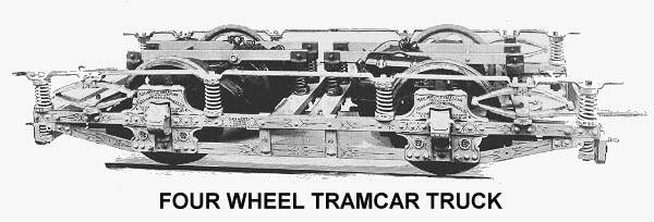
Generally speaking the four wheel truck consists of an outside frame that holds the wheels in place. Each axle is driven by a separate motor. The motor is mounted on the axle with a spur gear drive, the other side of the motor is supported on a sprung bar that fits across the truck. This helps to reduce the unsprung weight on the axles (important to reduce track damage). In the early days of tramcars the wheelbase of the truck was short, from 5ft 6in. As technology increased the power of motors, trams could became bigger and the wheelbase longer (giving a smoother ride). So examples of all wheelbases from 5ft 6in to 8ft 6in exist in 6in steps.
As the wheelbase increased, the tramcars experienced more difficulty in getting round tight curves. So manufacturers developed the flexible or radial(pivotal) truck. The idea was that the axles could move and would align themselves to the radius of the curve, straightening up when the tramcar was back on straight track. Unfortunately whilst the idea worked well on new trucks, the rigours of service meant that the system did not operate properly, often locking in the curve position. So many operators with these types of trucks fixed them as rigid.
 A simpler and better alternative was the pendulum or swing axle truck which had a link from the top of the journal box with a pivoted connection to a spring plank below, which in turn was sprung to the underside of the truck frame. This enabled the axle to have considerable lateral movement independent of the side frames, i.e. from side to side across the width of the car. Pendulum suspension was used on the very successful Peckham P22 truck and most of the later Peckham designs, both 4-wheel and bogie.
Thankfully in modelling we do not worry about radial trucks and the like. All our four wheel mechanisms are of the ordinary type. For 'OO' gauge operation there is quite a good choice for mechanisms. Of course being awkward, we have yet more terms for these. You will find that the mechanism for a model tramcar is called any one of these:-
Mechanism, chassis, power unit, traction unit, bogie*, SPUD*, drive unit, motor.
* when referring to the Tenshodo
For the 'OO' gauge modeller there is almost as much choice for the make of mechanisms as there are names. All are inside bearing. That is the axles are held in place inside the wheels. So the unit fits between the trucksides, which on the model are dummy, with no operational parts. The choice of units are:-
BEC (now KW), made for two rail operation, but easily converted to live overhead. The traction unit comes in a whole range of suitable sizes; 24mm, 26mm, 27mm, 28mm, 31mm, 32mm, 34mm and 42mm.
Mehanotehnika, the two rail mechanism from the American Birney car. This is 40mm wheel base and the motor fills the tramcar. Not really suitable and becoming difficult to find.
Tenshodo, made for two rail operation but easily converted to live overhead the unit (called by the model railway trade a bogie), the unit is widely available. It is offered in wheelbases of 24.5mm, 26mm, 28.7mm, 31mm and 35mm.
Halling produce a number of suitable motor units.
ABS. Very similar to the BEC, but in kit form, some soldering is required. The unit uses a white metal chassis. It is offered in wheelbases of 24mm, 26mm, 28mm, 30mm and 32mm, there are also custom made kits for motorising the EFE Horsfield and the Corgi 4 wheel trams.
BOGIE TRAMCARS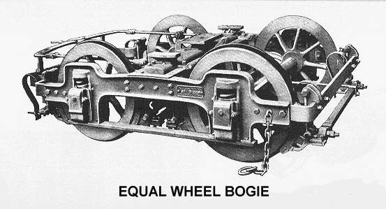
Once again there is an immediate sub division. Bogies come in two sorts, equal wheel and maximum traction. Equal wheel bogies have as the name suggests two axles with four wheels, the wheels being all the same diameter. The bogie is pivoted about its centre. Each axle has its own motor, so a normal equal wheel bogie car would have four motors. They are found on early bogie cars, when motors were less powerful, and on tramcars in towns where there were steep hills.
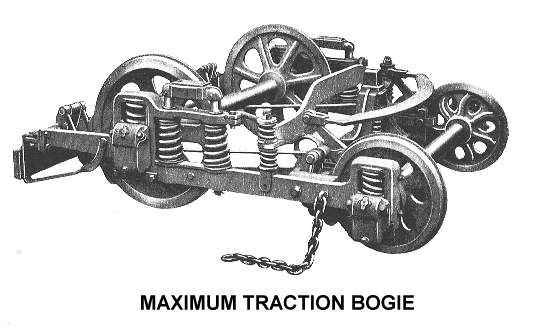
The maximum traction bogie was developed as motors got more powerful, and it was felt that a bogie car could be powered using just two motors. So the maximum traction bogie has just one motor. There are two large wheels and two small wheels, and it is the large wheels that are driven by the motor. In order to get the maximum power from the motor the bogie is pivoted nearer to the large wheels. This places more of the tram's weight on the driven axle and gives more power, hence the name maximum traction. In fact the traction power was always much less than that of an equal wheel bogie with twice as many motors.
The difference was demonstrated very well in London, where most of the tramcars were of the maximum traction type. But on the hilly routes a special type of tram was used, the HR2, with equal wheel bogies. The HR stands for Hilly Route.
In the 'OO' gauge model it is usual that only one axle of the bogie is driven, irrespective of whether it is maximum traction or equal wheel (I said all this was confusing!). Like the four wheel chassis the model bogies are all inside bearing and the bogie sides are decorative not functional. For the 'OO' gauge modeller the following power bogies are available:-
Bachmann, The equal wheel bogies from the Brill, PCC and San Francisco Cable Car can be used, though the motor is large in the first two. 22mm wheel base (I do not have the size of the cable car bogie).
BEC (now KW), a range of two rail powered bogies is available. Equal wheel 18mm and 21mm wheelbases. Maximum Traction 18mm wheelbase.
Lima and Roco, offer six and eight axle articulated chassis which are very nice, using a motor mounted separately from the bogie. But at around 90 - 120 pounds per tramcar there are much less expensive ways of getting motorised equal wheel bogies.
Mehanotehnika, the Boeing LRV chassis can be used, though the motor is large and is mounted separately from the bogie, with a flexible drive. It is a source for articulated chassis with equal wheel bogies and the price, around 30 pounds is far less than any other articulated chassis.
Tenshodo, the smallest two rail Tenshodo (24.5mm) can be used in some equal wheel bogie models.
Halling produce a number of suitable motor units.
THREE-AXLE TRAMCARS (by John Prentice)
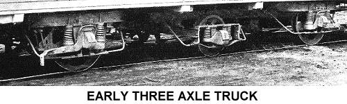
Further to the above description of four wheel radial trucks, another idea was to have three axles, the central pair of usually smaller wheels acting as a guide to move the outer axles to the radius of the curve. Three-axle trams are often regarded as a failed experiment. In the UK this is correct, but not so elsewhere. Around 300 cars were built in the US before 1900 and over 1250 in Europe after 1925.
The first serious mention in connection with tramways comes from the British civil engineer James Cleminson of London who in 1876 was granted a patent entitled "Articulating or Mounting Railway and Tramway Axles and Wheels, &c.". This patent includes a number of methods by which the axles could be linked. Cleminson's design was not used to any great extent on trams, but was tested in Dublin under horse car 125, and certainly found favour with narrow gauge railways.
In the US and the pioneer of this type of truck was William Robinson of Boston, who in 1881 was granted his first patent (of many) for a six wheel radial truck which he then proceeded to market to various tramways during the next ten years or so, producing around 200. A further 100 were built by the Boston West End Street Railway to a similar design, which Robinson considered to be an inferior copy of his truck. By the end of the 19th century the 3-axle design lost popularity in favour of bogies and 4-wheel trucks and radials, and its use came to an end.
In the UK there was only one electric design. During 1909 and 1910 car 52 of the London United Tramways (see Historic Photo) was fitted with a three axle radial truck of 12 foot wheelbase from British Radial Axle Cars Ltd., designed by Thomas Walter Barber of South Norwood. A similar truck (possibly the same one modified to 11 foot wheelbase) was tried from 1911 to 1913 under sand car 05 of the Metropolitan Electric Tramways. An 11 foot wheelbase broad gauge version was used in Dublin under car 286 in 1911-12 and another truck was thought to have been tried in Southampton under car 57 circa 1910. In mid 1913 the Barber's company was wound up.
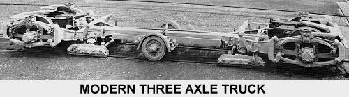
In Europe in Gent, Belgium between 1925 and 1932, third axles were added to improve riding to 105 4-wheel radial truck cars. However, the big advance was when the three-axle idea was redeveloped by a Swiss, Jacob Buchli of the Schweizerische Locomotiv und Maschinenfabrik of Winterthur (SLM) in 1929, who applied modern techniques particularly in respect of the motor suspension. This design was used on a number of SLM cars in Switzerland and elsewhere, including 110 trams and trailers for Amsterdam built under licence in 1949/50 by Werkspoor. In Germany, Westwaggon took up the Buchli design in the 1930s and produced large numbers of cars for various systems including modern cars post World War II. Finally more than 500 three-axle trams and trailers with Buchli style trucks were built by Rathgeber between 1949 and 1965 forming the Munich class "M".
REVERSIBLE HORSE TRAMCARS (by John Prentice)
The principle of the reversible truck is simple. With double ended horse trams, at the terminus the horse or horses have to be uncoupled from the front complete with all the harness, walked to the other end and then be coupled up again. In a reversible car the body has a central pivot point on the truck and at the termini the body itself is unlatched from the truck and is pulled round by the horse(s) without the driver having to leave his driving position. An additional bonus is that the car can be lighter than a double ended car and in the case of a double-decker needs only one staircase. A disadvantage is that the weight distribution of the body has to be carefully balanced or the whole thing would tip up when the body was at right angles to the truck.
In the US John Stephenson built reversible cars in the late 1850s and in 1859 patented a brake system suitable for one. Henry Casebolt in the 1860s produced "balloon cars" for his Sutter Street Railway Company in San Francisco. The most famous builder of reversible trucks was John Eades who was a coach-builder and the manager of the Pendleton works of the Manchester Carriage Company. In 1877 he produced a prototype of his reversible tram and tested it in Salford. In June of that year he filed for a patent which with minor amendments was granted in December. The body rested on the truck both being fitted with circular and segmented plates and a fulcrum bolt (f in the patent drawing) upon which the car swivelled. Beside the driving position there was a lever which locked the body to the truck. Braking was as in a normal horse car with brake beams, a sway bar and pull rods, but the chains between the pull rods and the brake staff would be unhooked by the conductor when the car was turned. At the trailing end there was an emergency brake wheel mounted on the nearside saloon bulkhead similarly linked by a chain that could be unhooked. The sway beam was slightly extended to the solebar where a hinged rack device could be engaged to hold the brakes on during reversal. Wheels on one side of the car were free to revolve on the axles to provide a differential effect.
Over 500 Eades cars of similar design were built by the Manchester Carriage Company for use in the Manchester and Salford area (see Historic Photo). In addition many more Eades trucks with various bodies, a few single deck, were built under licence by the Ashbury Railway, Carriage and Iron Co. Ltd. of Openshaw, Manchester. In addition to Manchester and Salford, places where Eades reversible trucks were used include Liverpool, Leeds, Bradford, Stockport & Hazel Grove, Chesterfield, Wallasey, Sheffield, Dundee, Newcastle, South Shields, Sunderland, the North London Tramways Company and the Tramways Sud in Paris.
| Go to ---> |