Starting & Stopping
Tramcar Controllers and Brakes
By John Prentice
|
CONTROLLERS
When an electric motor is at rest it has a very low electrical resistance. If you were to apply the full line voltage, it would certainly be damaged. You have to increase the current gradually. Once the motor is turning it acts as a dynamo and the voltage (electro-motive force) generated, known as back-EMF, opposes and limits the current flow.
Now the first electric trams were controlled either by a rheostat or simple notched resistance controller (as used on the first British street electric tramway in Blackpool in 1885) or by "comutated motors", which had three field windings switched into series or parallel combinations.
In the United States in 1891, William J. Hopkins and Theodore Stebbins filed for a patent (granted in 1894 as number 520,784), assigned to the Thomson-Houston Electric Company, for a controller using series and parallel motor connections together with resistances. By 1892 Thomson-Houston were advertising their Series-Parallel controller, "a great advance" promising a "saving in power of about 35% over the rheostat or comutated field methods". This method quickly became standard and was the accepted system by the time of the boom in building of British tramways at the end of the nineteenth century.
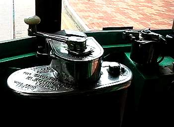
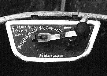 This is the first type of series-parallel controller from Britain's Dick, Kerr, a DE1 Form B made in 1901 but was in fact an import from America from the Walker Electrical Co. of Cleveland, Ohio (owned by US Westinghouse from 1898), who made equipment for Dick, Kerr from 1898 to 1901. The top plate was probably cast at Preston and carries the English Electric name which was used until 1903 and again after 1919. The "Short System" refers to Professor Sidney H. Short who had by then joined Dick, Kerr from Walker. (Photo by J.Prentice ©)
The controller is supplied with power from the Current Collection System via a current limiting automatic circuit breaker, usually fixed to the underside of the canopy roof, just above and behind the motorman (driver). The controller has a handle on top and this turns a drum fitted with insulated copper segments, onto which press brass fingers fitted with copper contact tips. There is usually a star wheel and roller which ensures that the drum advances in notches to match the drum segments, sometimes incorporating devices to ensure that the motorman "notches up" just one notch at a time.
 A typical Series-Parallel drum controller, this one made by Siemens. The view on the right has the casing removed and the arc shield swung back to reveal the drum segments and fingers.
On the Motorman using his left hand to move the controller handle clockwise from the "off" position, at first the two motors on the tram (or if a four motor car, two pairs of motors) are connected in series with each other and with a large resistance. As the controller handle is moved further clockwise, the resistance is systematically cut out until the motors are in "full series" i.e. no resistance. There is then a section of the controller, known as the shunt-transition, during which the motors are switched into parallel and the resistance is replaced. Again as notching up continues the resistance is cut out until we are on "full parallel". A tram can be driven continuously on "full series" or "full parallel" but must not be held on the resistance notches or current will be wasted and more importantly the resistances will overheat. If the controller is moved anti-clockwise past the "off" position, it engages additional notches to provide braking, which we will consider later.
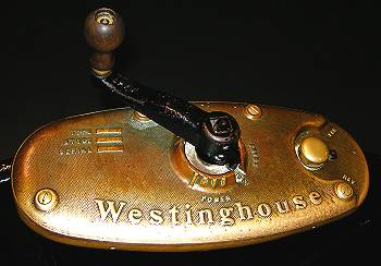 Here is a Westinghouse T2G controller as fitted from 1906 to many trams in the fleet of West Ham Corporation. This particular example is on car 102, built 1910, which is in the collection of the London Transport Museum. (Photo by J.Prentice ©)
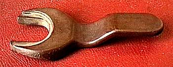 London controller key as used on Westinghouse and MetroVick controllers. (Photo by J.Prentice ©)
A second drum on the controller is operated by a key and has positions for "forward", "off" and "reverse". The key can only be removed in the "off" position, which also locks the main drum. The motorman can then take the key, and on some early controllers also the handle, to the other end of the car for the return journey.
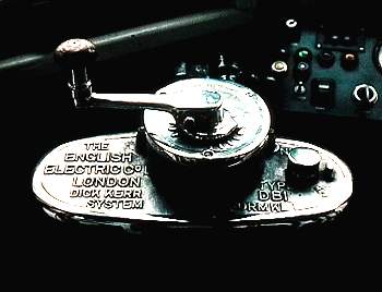
 A General Electric Form K11 controller from a batch made in the USA at Schenectady in 1898 for the Manx Electric Railway. It is now fitted to car 19, a "Winter Saloon". (Photo by J.Prentice ©)
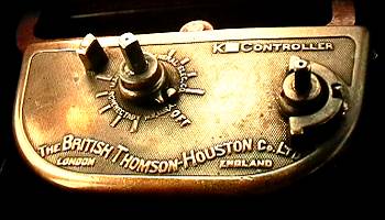 A similar but slightly later K12 controller on the Manx Electric Railway made by General Electric's English subsidiary, British Thomson-Houston. (Photo by J.Prentice ©)
Controllers usually incorporate arc shields and after 1897 magnetic arc blowouts (invented by Professor Elihu Thomson of Thomson-Houston), to prevent arcing when the circuits are broken. There is also a set of contacts which enable to motorman to cut out one motor in the case of failure, in which case the car can be driven up to "full series" on one motor only. Controllers had brass, sometimes chromed, top-plates indicating the various functions and maker's names.
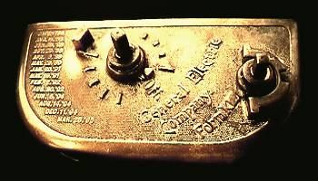
 Here is the top plate of a British Thomson-Houston B49 controller from around 1920, with reversing key fitted, and showing four series and four parallel "power" notches, seven "brake" notches and a motor cut-out spindle.
At first most electrical equipment for the British tramway boom was imported from the more technologically advanced United States, but by around the turn of the century the demand was such that British companies began manufacture, initially to US designs but later to their own. The main British producers of controllers were:-
- Dick, Kerr & Co. (later English Electric) of Preston
- British Westinghouse Electric and Manufacturing Co. (later Metropolitan-Vickers or MetroVick) of Trafford Park
- Brush Electrical Engineering Co. of Loughborough
- British Thomson-Houston (the UK trading name for the US General Electric) of Rugby
- General Electric Co. (no connection with the US General Electric) of Witton, Birmingham
 This is a Dick, Kerr DB1 Form K3 controller with a Maley & Taunton brake interlock. It dates from around 1925, but is seen here in 1993 on a Lisbon car. Most of these have now been withdrawn. (Photo by J.Prentice ©)
 Another Dick, Kerr DB1 controller, this time a Form K4E with a slightly different Maley patent brake interlock and showing the separate air brake handle. It dates from around 1930, but is seen here still in service in 2005 on Hong Kong car 120. (Photo by J.Prentice ©)
From the 1920s as motors became more powerful and the currents involved larger, all manner of mechanical (cam), electrical or even pneumatic contactors were tried, followed by automatic acceleration multi-notch systems, but by then British tramways were in decline, so the simple drum controller remained the most common method until system closure.
 An OK-B cam contactor controller from the 1920s, made by British Thomson-Houston. The spindle of the handle passes down through the reversing drum at the top, and using bevel gears turns a horizontal cam shaft across the centre of the controller. The cams on this shaft close the contactors, which are normally held open by springs.
Resistances
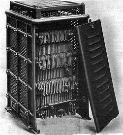 An under-stair resistance box. The front cover has been removed to reveal the coiled up steel strips of the Maley patent ribbon resistance held within. This example was made by EMB in the 1920s.
Resistances were initially made of cast iron sections bolted together with many joints and then insulated as necessary. These where liable to frequent breakage causing car failure. In 1909 A.W.Maley designed and patented (British patent 23,216 of 1909) a resistance using a continuous ribbon strip of sheridised high-carbon steel which was bent up and formed a grid with no intervening joints. The grids were separated from each other by mica washers and held in place by bolts in mica tubes. The resistance was air cooled. On double deck cars it was contained in a cabinet under the stairs at one end. On single deck cars it was under the floor. Very exceptionally it could be mounted on a car roof. This resistance was sold in thousands by EMB and Maley & Taunton and became the industry standard.
Sand
In passing we should mention sand. In emergencies the driver could use a foot treadle (next to a gong pedal) which released fine dry sand. This ran down pipes and onto the track just in front of the wheels to increase the grip and stop slipping. Sand could also be applied to stop the wheels spinning on starting the tram, if the track was greasy or slippery. The sand was stored inside the car in hoppers (sandboxes) under the end seats. Some later cars had power operated sanding which could be initiated from the driver's controls.
 Go now to Brakes
 Return to Start
© Copyright John R. Prentice Software 2007