
By David Voice (with additions by John Prentice)
|
|
CURRENT COLLECTION
By David Voice (with additions by John Prentice) |
 Early Days
In the early days of electric trams the builders had not properly worked out how to get the electrical power to the tramcars. When Volk's Electric Railway opened in 1883 Magnus Volk used a two rail power supply. This was not successful as in wet weather the current would leak across the sleepers. So he turned to three rail, able to do so because the whole of the track was away from public access. The Giant's Causeway tramway, also opened in 1883, used the three rail system. For the street running in Portrush there was no electrical supply and steam tram locomotives were used to pull the tramcars. Bessbrook and Newry (1885) also used three rail, though at level crossings an overhead wire was erected, and the electrical supply collected by an early form of bow. This was rigid and relied on the droop in the overhead wire for contact.
The idea of putting the electrical supply up in the air, safely out of harms way was appealing. The return current would go via the rails. But there was always the problem of getting the electricity from the overhead wire to the tram. An early solution was to put two wires up and to pull a little trolley along with wheels running on the wires. The trolley (sometimes called a troller) had a habit of coming off the wires and dropping to the ground, so the connecting wire to the tram was long, to ensure that when it came off it did not hit the tramcar. The crew became quite adept at using long poles to get the trolley back onto the wires. There were other ingenious but not entirely practical solutions to the problem until the trolley pole as we know it was perfected in 1887 by Frank J. Sprague in the US for the line at Richmond, Virginia. (See also Charles J. Van Depoele).
In Britain overhead wires were required to be 20 feet from the road surface (by special agreement with the inspectorate the wire could be lower, for example when going under low bridges). The modern tramway systems that have been opening over the last few years have gone metric, with European Community regulations, and the height is now 5.8 metres (about 19 feet).
Trolley Pole Collection
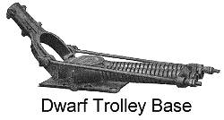
The trolley pole is an ingenious solution to the problem of getting power from the overhead wire to the tram. All trolley poles are attached to the tramcar with springs that push the other end of the pole upward. At this end there is either a wheel or a skid that has a groove which fits under the wire. The springs push the wheel or skid against the wire and can compensate for variations in the height of the wire. Lateral movement of the tramcar in relation to the wire is allowed by letting the trolley pole swivel at the tram end. On trams with roofs, the springs are usually easily seen. On open top trams, the springs are usually hidden inside the tram mast.
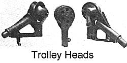
At the wire end, the trolley pole could be fitted with a fixed head, swivel head or skid. The fixed head has a wheel where the groove is always in line with the pole. On swivel head trolley poles, the wheel is mounted on a small fixture that can rotate in relation to the pole, so the groove can stay in line with the overhead wire. These were often found on side running overhead systems, where the overhead wire is held close to the pavement and the trolley pole had to reach over the road to contact the wire. Skids are a later innovation, developed for trolleybuses, the skid has a swivel head with a grooved carbon block to give a good electrical contact with the wire.
At a stub end terminus the pole has to turned around ready for the trip back.
Bow Collection
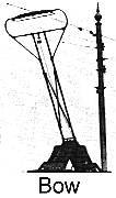
Early bow collectors were either rigid or had little springing. However, they were soon developed into reliable operating devices. Bow collectors use the same idea of springs pushing the bow up to the wire. However, there are usually two rods with a collecting pan that slides under the wire. The pan sits at right angles to the wire and the lateral movement is allowed by the wire sliding across the pan. At the terminus, the bow will usually push up the wire and flick over when the tramcar moves in the opposite direction.
The way the overhead wire is mounted must be a little different to the trolley pole system. For bows, the wire must always be near the centre of the track, otherwise the bow cannot touch it. On the other hand there is no need for the complicated type of overhead frogs that trolley poles require. Bows were far more popular on the continent of Europe than in Britain. Major British users were Aberdeen, Glasgow and Leeds.
Pantograph Collection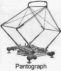
Pantographs are rather like bows, except the collecting pan is raised directly vertical rather than in the arc of a bow. The same comments apply on the positioning of the overhead wire as the bow.
Again for traditional tramways pantographs were more popular on the continent than in Britain, although Sunderland did use them extensively. In more modern times the pantograph has become the standard, usually in a single arm variety. So all the new tramways use it and even Blackpool has converted most of its trams to pantograph operation.
Conduit Collection
In some towns and cities, the councils did not want their street made unsightly by overhead wires. So systems were developed to hide the electrical supply.
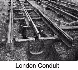
The longest lasting system in Britain was the conduit, where central London was entirely fitted for conduit operation. Here there is a small tunnel under the track with a slot running parallel to the rails. In some systems, like London, the slot was between the rails, usually but not always in the centre of the track. On others the slot was incorporated into the groove of one of the running rails. In the tunnel there were two collector bars, one positive and one negative (the running rails were not used as the return). Hanging under the tram was a plough, which was a device that fitted into the slot and had collector shoes that touched the collector bars. Wires from the plough to the tram allowed the current to get to the motors.
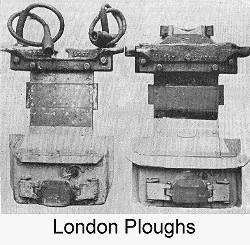
In London there was the added complication that the outer parts of the system were powered from the overhead. Where the conduit finished and the overhead began there were change pits. These allowed the plough to taken off the tram for cars going onto the overhead, or be fitted with a plough in the other direction. Apart from a small number of early trials, London was the only place in Britain that had the conduit. It was somewhat ironic that on many conduit routes, the trams were replaced by trolleybuses, which used twice as much overhead wiring as the trams would ever have used.
Surface Contact Collection (by John Prentice)
Another attempt to do without overhead wires was the surface contact system. Here metal studs were placed along the centre of the track at about 10 feet intervals. Under the tramcar there were metal skates around 12 feet long (so it always had contact with at least one stud), which collected the current. Now to prevent other road users from being electrocuted, the studs were normally switched off. When the tramcar came along, powerful electromagnets under the tram operated switches that turned on the studs at the right time, then when the tram passed the switch would turn off. This was the theory. In practice the switches proved unreliable and often left the studs live and many a horse got electrocuted. In an attempt to stop this, the tramcars were fitted with metal brushes that shorted out any live studs or sounded an alarm on the tram.
In some alternative systems of surface contact current collection, instead of magnetic activation from the tram, pick-up studs or contact rails in the road between the rails are activated by some form of remote electrical switchgear at the track side, such as the Krizic system on Charles Bridge in Prague (1905-08), the Thomson-Houston system in Monaco (1898-1903), the Murphy Third-Rail system tested at Coney Island, US (c.1898) and indeed on the new system in Bordeaux, France.
The Anderson system was tested in Leeds in 1896, consisting of mechanically connected studs where the one in front of the tram was pushed up out of the road surface by the action of a skate on the tram pushing down the one behind. The Lineff surface contact system was tested by London's West Metropolitan Tramways in 1890 in Chiswick depot, and consisted of a closed conduit containing a power cable, which was electrically connected to a sectionalized third rail when the tram carrying an electromagnet passed over it. The mechanical Kingsland stud of 1899 and the magnetic Suchostawer stud of 1907 were both British improvements on stud methods which were demonstrated but never actually used, although the latter was proposed for Dover.
Stud contact was used briefly in a number of locations in Europe and the US, with in Paris some more extended use using various systems (Claret-Vuilleumier, Védovelli, Dolter, Diatto) between 1896 and 1914.
In the UK all the stud systems in public service were of the magnetic type. The French Dolter system was used in Mexborough (1907-08), Torquay (1907-11) and Hastings (1907-13). The English Griffiths-Bedell system was used in Lincoln (1905-19) and on a failed trial for the London County Council Tramways on the Mile End Road in 1908 - see Historical Photos of a stud and a tram. By far the most successful of all was the use of the American Lorain system in Wolverhampton (1902-21) with 58 surface contact equipped trams and 14 miles of route, 22 of track including many gradients, curves and junctions.
These stud systems are more fully described in our Postcard of the Month series:
Trolleybuses on Tram Tracks (by John Prentice)
When trolleybuses were originally introduced, it was sometimes found necessary to manoeuvre them by using one trolley pole on the tramway overhead and obtaining an electrical return by connecting to the tram tracks using a skate or slipper. For Leeds and Bradford, the first British trolleybus systems in public service and built by Railless Electric Traction (RET) in 1911, Edward May Munro, formerly of Brecknell, Munro & Rogers Ltd., designed this current collector to allow trolleybuses to reach the tram depots by using the tram tracks. The drawing is from Munro's 1911 patent.
The unit was connected to the trolleybus by means of a hollow shaft containing the power supply cable and which was pivoted at both ends to allow the vehicle a reasonable amount of sideways movement to either side of the tram rails, without becoming disconnected. The unit itself consisted of two sub-assemblies, which were vertically sprung to provide a good but flexible connection to the track. There was a pilot member consisting of a steel bar which engaged with the track groove followed by a laminated copper / carbon brush pickup and finally by a flanged wheel running on the off-side tram rail. All these three were electrically connected. When not in use the whole unit was raised up clear of the road and suspended by a shackle at its top from the underside of the vehicle.
Modelling
To my mind there is no better sight than seeing a model fitted with a trolley pole running around a layout. The trolley pole seems to have a life of its own. In all the popular modelling scales there are commercially made trolley poles and overhead fittings. Commercial Bows and pantographs are available for the smaller scales.
Modelling conduit and surface contact is very easy. Most modellers use two rail operation and represent the conduit groove or studs with paint or plastic parts. However, to be authentic the layout would need to represent a system that actually did use this type of current collection.
Useful addresses for modelling parts for current collection are:-
Images used in this article are courtesy of John Prentice.
| Go to ---> |