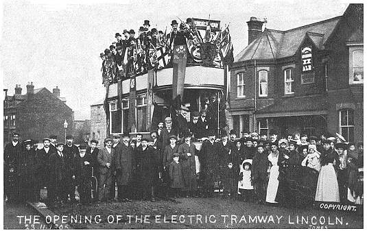

This postcard was produced by a local photographer by the name of Jones for the opening of the electric tramway in Lincoln on 23rd November 1905 and our example was posted exactly one month later. The standard gauge tramway was built for Lincoln Corporation by William Griffiths & Co. of Ilford in Essex, replacing an earlier horse tramway. The single route was just under two miles long. There were only eight trams, six open top and two open balcony, all built by Brush for the opening. They had 22 seats inside and 30 on top and were on Brush Conaty 4-wheel trucks, each with two Westinghouse 25 h.p. motors and using Westinghouse controllers. The livery was pale green and cream. (See Historic Photos for other views of the Lincoln opening).
The unusual feature of the tramway was its use of the Griffiths-Bedell patent surface contact stud method of current collection. As in all magnetic stud systems, the basic principle is that the tramcar carries a current collecting shoe or skate which is magnetized by powerful electromagnets. When the skate is over the stud, the electric circuit is completed by movement of an armature and the stud becomes live, supplying the car with power. Once the car has passed, the stud becomes dead again. In the case of the G-B system there was a wire brush device at the end of the car and if the stud was still live when the brush touched, an alarm bell sounded on the car to warn the crew.
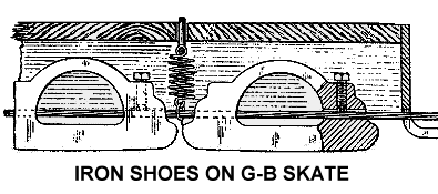
 The current collector mounted on the car consisted of a number of iron shoes fixed with pinch bolts to a hemp-cored wire rope that was made off at the ends to insulated shackles and held up at intervals by springs. As the collector passed over the stud head, the magnet field from electromagnets caused the iron shoes above to be drawn down and make electrical contact with the stud head at the same time as the stud was switched on. The electromagnets (initially four) were powered by the traction supply, with a rechargeable battery for when there was a supply interruption.
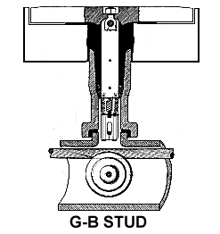
 The G-B stud head was made of cast iron, and was 2.5 wide inches by 10 inches long, supported by 8 inch by 16 inch granite blocks. Attached to the head by an eyebolt was a stalk formed of laminated iron plates. At its lower end it formed a fork, the insides of which were lined with brass plates. Between these was the switch armature made of galvanised soft iron plates. The armature was suspended from the stalk by a copper plated steel coil spring adjusted to just support the armature at its highest position. It was insulated from the armature to avoid current passing through it. There was a slot in the armature where a pin passed through to limit the armature movement. At the bottom of the armature was a carbon block held in a copper clip (copper contacts in the original design) to provide the electrical switch contact. Electrical connection was made to the head by flexible copper conductor leads. Once magnetized by passage of the skate, the armature moved downwards to contact the cable below, with it being drawn upwards by the spring when the tram had gone. It was suggested by the designers that residual magnetic flux would blow-out any arc that might form. The whole assembly was contained in a stoneware pipe. At the bottom of the stalk the space between it and the stoneware pipe had packing driven in and the space above up to the head was filled with melted bitumen.
The studs were laid at about six feet intervals fixed to a horizontal stoneware oval conduit about 6 inches by 5 inches through which ran a galvanised stranded steel power supply cable, one and three sixteenth inch in diameter. It was this cable that the armature was attracted to. The joint between the stud and the conduit was sealed with bitumen. Under each stud the cable was supported by a circular insulated roller. The centre support for this insulator was a galvanised steel pin which was earthed to the rails by galvanised iron strips for safety. The original idea was that the cable could occasionally be pulled through the conduit by a small amount to bring a new contact surface into use. In practice it was found that the electrical contact with the irregular shaped cable was unreliable, so after 1907 the cable was fitted with a galvanised iron sleeve at the contact point. At intervals along the line there were access boxes were the cable was divided and where the conduit could be drained of any water that had got in.
In common with all magnetic stud systems, pieces of metal rubbish in the roadway such as hat-pins, nails, bolts, wire, pieces of scrap iron etc., are attracted and stick to the car magnets. At crossovers and junctions, when the skate has to cross the running rails, this rubbish can cause short circuits. On the G-B system stud heads at junctions were supplied via resistances which would limit the current flow in the event of a short, but at the same time would pass sufficient current to slowly move a tram across the junction.
The only other G-B stud installation was that of the L.C.C. tramways on the Mile End Road in 1908, (see Historic Photos of both a stud and a tram on trial), but there it was a failure and was withdrawn after just one month.
Due to maintenance difficulties during WW1, it was decided to replace the studs with overhead current collection and this was completed by Dick Kerr in 1919, at which date three new open balcony cars were purchased from English Electric. Despite this expenditure, the Lincoln system closed ten years later on 4th March 1929, with car 6 as the last tram.
![]() Go to Postcard Of The Month Index
Go to Postcard Of The Month Index