Taken from US patent number 169,816 of 1875, this is what Leveaux envisaged his clockwork tram would look like. Note the winding gear in the box below the road surface.
|
The Clockwork Tram
By John Prentice |
How did they find a big enough key? This must be a wind-up - ugh! No, not a joke or April Fool's Day article, early inventors did indeed consider clockwork, or more correctly spring power, as a stored energy method for driving trams. Trials were undertaken but alas no clockwork tram ever ran in public service.
The idea of a spring powered tram originates from a design by a Belgian, Edward Henry Leveaux, who in 1873 was granted British patent 3123 for his "Improvement in Car-Propellers" (also covered by US patent 169,816 of 1875). Leveaux was then living in Brook Green, Hammersmith, England. In 1874 engineers Thomas Middleton and Co., of Loman Street, Southwark, constructed a machine to this design. It was demonstrated pulling a passenger car at the Lillie Bridge depot of the Metropolitan and District Railway in May 1875.
A small stationary steam engine of about 5 horsepower wound a series of compound coiled springs in barrels, coiled in opposite directions to provide constant power. A maximum speed of 7 mph over a half-mile run was obtained on one winding with six springs (two sets of three barrels) on a 5-ton car. The last test in 1876 achieved a two mile run using 24 springs.
On the platform of the car were two levers. One provided, via clutches and spur gears, the means to reverse the car. The other released a brake on the the spring drive and allowed the car to start. The tram had conventional wheel brakes for stopping. The winding shaft was fitted with a pawl and ratchet wheel as in a clock. At each end of the track and if necessary at other stopping places, the springs could be wound up. The stationary engine turned a shaft below the road surface. This drove spur gear wheels which were mounted on a radial arm in a box beside the tram track and which could be swung upwards through a trap door. A sleeve on the upper spur wheel engaged with the end of the winding shaft.
The Leveaux British patent document also includes a comment and diagram showing that the spring mechanism could be mounted in a tender to push and pull a carriage and it is assumed that it was something like this that was used at Lillie Bridge. Many such tenders could be kept ready wound for use as required, avoiding the need to delay the vehicle while winding took place.
Later Leveaux, then living in Clapham, took out another patent (GB 796 of 1879, US 247,993 of 1881) for an improved version of his spring mechanism with examples for driving machinery such as sewing machines as well as carriages. He was also involved with mechanical pianos such as the "Angelus", manufactured from 1897 in the United States, which derived its power from such a device. The improved version, by employing a chain wheel drive with band brakes, had the ability to wind and use the barrels individually, providing variable speed or power. It had indicators to determine the state of winding of each barrel. A worm drive was used in the winding mechanism.
A similar vehicle was considered by a number of people in Philadelphia, Pennsylvania in the United States. Although no conclusive link can be made, it is probable that they were all connected and in fact were working towards a single Philadelphia car.
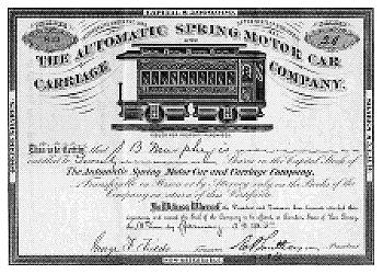
Around 1885 the Automatic Spring Motor Car & Carriage Company described their plans to construct a streetcar with eight barrels of ten springs each, which they thought would run for at least 8 miles. The car would have a governor to limit top speed, but the power could be provided from individual barrels as required by the loading. It was also thought that downhill running and braking might possibly be used to rewind the springs, although conventional brakes would be fitted. A single spring breakage would not decrease the power very much and it was stated that springs could easily be replaced in about two hours for a cost of five dollars. It was claimed that just two stationary steam engines each of 15 to 20 horsepower would suffice to run a city railroad, leaving spare capacity to supply their workshops in slack periods.
In 1883 George Jiencke, a German citizen resident in Philadelphia, had been granted US patent number 273,365 for "spring-motors designed most particularly to drive street-railway cars". This patent was assigned to the American Spring Car Motor Company of Camden, New Jersey, but the car details explained in it very closely match the proposals of the Automatic Spring Motor Car & Carriage Company as stated above. The mechanism would have had a series of spring barrels set longitudinal to the car body as opposed to transverse as in Leveaux's design. The drive passed to the wheels by means of bevel gears to an intermediate shaft fitted with a band brake, then a two speed chain drive to the wheels. The multiple barrels, which could have been extended to form several rows, were constructed to provide a continuous power output over an extended period of time.
Later in 1883 Daniel M. Pfautz of Philadelphia was granted US patent number 282,919 for a spring-motor as applied to a street-car. This patent was 52 percent assigned to Jacob J. Gumpper, William M. Maul, George F. Fields and J. Francis Bacon, all of Philadelphia. The last named gentleman was in fact a director of the American Spring Car Motor Company. This patent included the speed governor and the ability to use individual springs mentioned in the proposals of the Automatic Spring Motor Car & Carriage Company. The springs were mounted longitudinally in groups to either side of each separate axle, which was directly driven by bevel and spur gears. Apart from that it was quite unusual. The front axle of the car was radial to assist turning curves being steerable using a rack and pinion. The wheels had extendible spikes on the inside of the rims that could dig into the road surface to provide extra traction on wet or icy track. It was to have been provided with a ratchet handle to wind the springs manually if necessary. Mr Pfautz may have known about springs, but he clearly knew little about trams.
It is not known if the Philadelphia car was to be built using Edward Leveaux's designs or if it was inspired by them, but the proposals certainly contain many of their features. Leveaux had taken out his patents in the US as well as the UK, and he had contacts in the States in connection with his automatic pianos, so it is quite possible.
In February 1885 Francis Bacon, on behalf of American Spring Car Motor Company, reported, "As with every new thing, difficulties have occurred which were not expected in the beginning. At the present time nearly all perplexities have been removed; the springs have been made and tested; a large car (except for the top or wood part) completed; and a final test will be made just as soon as the machinery can be properly adjusted." This is the last mention we have of a clockwork tram. Did the final test fail? By 1885 electric trams were starting to take a firm hold in the US, so perhaps the idea had just arrived too late.
The main historical sources for this article are Charles Klapper's "The Golden Age of Tramways" - 1961 and Frank Rowsome's "Trolley Car Treasury" - 1956. Technical details are from the British and United States patent documents and my thanks go to Bob Appleton for his help in locating some of these.