 |
Compressed Air Trams
By John Prentice |
|
|
Compressed Air Trams
By John Prentice |
In the 1840s several locomotive engineers, including I.K.Brunel, created Atmospheric Railways. These had a continuous pipe between the rails which contained a piston being pulled along by a vacuum. In the top of the supply pipe was slot with an air-tight flap (usually made of leather coated with tallow) through which a shaft passed, connecting the piston to the vehicle. The system was not a great success, one reason cited being that rats ate the leather flap. This method was never used for tramways, which preferred a self contained compressed air loco or car.
The idea is simple. First you create the supply in a central works where a compressor set, usually driven by a steam engine, compresses air to a high pressure and stores it in a battery of reservoir tanks. From this works, the air is distributed via mains, usually underground, to charge points at the tramway route termini. At these points the high pressure supply is fed in charges into the trams which themselves have reservoir cylinders or tanks which hold enough air for a complete journey. As required, air is fed via a pressure reducer and regulator to driving cylinders, similar to those of a steam loco, which drive the wheels.
The big problem with the above is temperature. When you compress air it gets hot and when you expand it, it rapidly cools. As the air is distributed at normal temperatures a lot of energy is lost in compression and decompression. It has been calculated that allowing for the losses due to the mechanism plus the thermal losses, the compressed air car has about a 30% efficiency of energy.
Another problem is that the rapid cooling when the air is used causes the pipes on the tram to ice up, and the lubricants used to go hard, causing seize-ups.
Compression: If the air is allowed to warm up too much there will be a huge waste of energy. To avoid this two methods were used. Firstly a spray of water was injected into the compression cylinders and mixed with the air in them. The spray on vaporising absorbs latent heat and keeps the unit cool. It can be shown that starting at 15 degrees C and compressing at a 4.3:1 ratio then the final temperature would be 180 degrees C with dry air and 70 degrees C with saturated air.
The second method of heat reduction was to use compression in several stages, allowing the air to cool between each. Compressors were driven by steam engines of around 100 h.p.
Air distribution: On the French systems the air was carried via underground mains to charge points by pipes of 60 mm diameter and 7.5 mm thickness. Losses over pipe lines were said to be about 1% with some charge points being quite remote from the central works.
At the charge point there was a coiled flexible copper tube which provided the connection to a cock on the tramcar.
Air use on the cars: For the working of the tram the air pressure is reduced from 80 atmospheres to 6 - 10 atmospheres, and is then exhausted to normal pressure. This would cause problems of icing etc., as previously stated, as a drop of 100 degrees C could occur. The solution is to heat the stored air.
The name we will hear the most in connection with compressed air trams is Louis Mékarski, who in 1872 and 1873 took out patents for his system. All the most successful tramcars were built to the Mékarski designs.
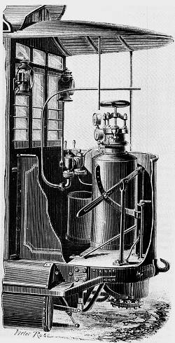 The Bouillotte and controls on the front platform of the earliest Mékarski cars. From a sketch by Victor Rose (1875).
The air from the reservoirs on his cars passed into an upright cylinder on the car platform nicknamed a 'bouillotte'. That is the French for a 'hot water bottle' (the thing you put in your bed) which at that time would have been a cylindrical bottle, not the rubber item we know now. (Note: Engineering in 1882 translates this as a 'hot pot.'). The bouillotte contained water under pressure and at a temperature of 160-180 degrees C. This not only warmed the air but also saturated it with water vapour. As this condensed on expansion, it gave up latent heat and limited the temperature fall. At the same time the condensation helped to lubricate the driving cylinder walls.
 A drawing of the regulator on top of the Bouillotte. The speed was controlled by turning the wheel and handle.
A regulator fitted with a hand wheel was fitted to the top of the bouillotte. This formed a screw which raised or lowered a piston inside, which in turn pressed a rubber diaphragm which operated a valve controlling the amount of air allowed into the driving cylinders, and thus controlled the speed of the car. Pressure gauges were fitted to the bouillotte showing reservoir and cylinder pressure.
At first water in the bouillotte was re-heated by passing through it a jet of steam, but later a Monsieur Bonnefond patented a method of fitting an internal coke firebox to provide continuous re-heating.
The whole idea of a compressed air vehicle was first developed by Andraud and Tessie of Motay in 1838 with a car running on a test track at Chaillot on the 9th July 1840. While it worked well, the system was not pursued and the idea was dropped.
Thirty years later the idea was revived by Louis Mékarski. To test his theories he first (in 1875) built a narrow gauge motor truck and tried it out on the gradients of a small industrial railway connecting La Maltournee to the Plateau of Avron in the suburbs of Paris.
 The original compressed air tram built by Mékarski and used in early trials. From a sketch by Victor Rose (1875).
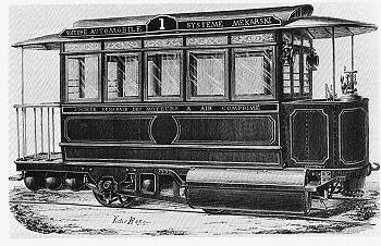
Following the success of this trial, Mékarski built a standard gauge self-contained tramcar (an automotrice in French) which was tested in February 1876 on the Courbevoie-Etoile Line of the Paris Tramways Nord (TN), where it much impressed the then president and minister of transport. The car was also shown at the exhibition of 1878 as it seemed to be an ideal transport method, quiet, smooth, no smoke, fire or fumes. This car was similar in design to the single deck horse cars of Compagnie des Tramways. The body was just 3.45 m long with longitudinal seats and carried 20 people inside, but there was a large rear platform with room for a further 14 outside.
 The bouillotte, taken from a drawing in Mékarski's US patent number 177,736 of 1876. The two larger dials give the air pressure in the main and reserve reservoirs, selected by the valves on the front. The top dial is the air pressure as supplied to the cylinders via the valve on the left. On the right is the water gauge tube.
Air at 25 atmospheres was stored in eight reservoirs 0.3 m or 0.4 m in diameter, mounted transversely under the car. These were in two sets, a main and a reserve set. The bouillotte was on the front platform and was 0.35 m in diameter and about 1.5 m high. It was three quarters full of water at about 180 degrees C. at about 7 atmospheres. The car had wrought iron frames 2.8 m wide and 5.6 m long and ran on 4 wheels of about 0.7 m diameter and 2 m wheelbase. The front axle was driven by two cylinders of about 0.125 m bore and 0.25 m stroke. The car weighed 4.75 ton empty and 7 ton with 30 passengers.
The air pressure was 5 atmospheres at the cylinders. Mékarski stated that his car would need about 70 kg of coal to charge the engine and about 5 kg to reheat the water.
Following this success, Tramways Nord used compressed air locos to pull horse trams on their Route E, Saint Denis to Place Clichy which began on 12th February 1879, but was soon withdrawn due to a number of incidents, possibly some with freezing brake lines.
At this point the story (and M. Mékarski) leaves Paris and continues at Nantes for the next few years.
![]() Go now to Next Section
Go now to Next Section
![]() Return to Index
Return to Index